Salve omnes. Do y'all know what it means? It's a latin word which means hello everyone. Forget to ask how are you all today? In good health? I hope so cause if not, you may not feel 100% enjoy when reading my latest blog ^^ .
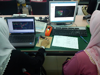
Well then, let's cut to the chase. To tell you the truth, this week in Electronic System class is quite a chaos. I was barely manage to snap several pictures for this week blog. Luckily I manage to complete the ultiboard test 20 minutes before class ended.
Lets's start from the beginning. As in the schedule, this week we have an ultiboard test. After learning how to use it, of course a test is needed to examine how far all of us understand ultiboard. After taking the attendance, Dr Redzuan distributed to us the question sheet. Y'all can see the question below :
Then Dr Redzuan explain about the question. He want to make several changes in the question such as components R5, L1 & L2 is put at the bottom of the circuit, components R3 & R4 use a surface mount device(SMD) footprint, the thrace size change to 25 millimeter instead of 10 millimeter as usual, and make sure that our board shape is not in SQUARE shape. Before we start the test, Dr Redzuan remind us to make sure that all components use are real.
Then, the test begin. To make the circuit appear in the ultiboard, first of all, we need to start with multisim. Take out all the component that we want in the multisim. You can see my components in the multisim before it's been arranged below:
Here the picture after it's been arranged :
After the circuit is done in the multisim, the next step is to transfer it to the ultiboard. Here you can see my circuit in the ultiboard before adjust anything :
Alright then. Next step, let's switch the board shape, and....... here's the result :
Now, with this hands(and mouse), I shall drag the components onto the board. After finished dragging & arranged the componets on the board, I need to click the autoroute function so that the ultiboard software will design the thraces on my circuit board. Here I put the final adjustment picture. You can see all changes in it :
Here is the explanation :
i) The wire-look that connected all the components is what we called thraces.
ii) The green thraces shows that the thrace is positioned at the top of the circuit board.
iii) The red thraces shows that the thrace is positioned at the bottom of the circuit board.
iv) The components that blue in colour shows that it is positioned at the top of the cicuit board.
v) The components that purple in colour shows that it is positioned at the top of the cicuit board.
Finally, the last step that need to be done before submit the ultiboard is to write our name on our circuit board so that when Dr Redzuan print out our circuit board, our name is written on it.
Like I told y'all in the last blog, the entice thing of the ultiboard is that we can view our circuit board in 3D!
I show to y'all the 3D view of my circuit board:
i) Top view :
ii) Bottow view:
From the middle view, y'all can see the components that was put at the top & at the bottom. But when I see it carefully while writing this blog, I just realized that I've made a mistake in the test. Supposely it should been three component that was put at the bottom but I just put two component; L1 & L2. I missed the R5. Now my mark will absolutely be deducted. It's too late to realized now. What's done is done. It can't be taken back. The only thing I can do about it is remember & learn from the mistake so that I will not repeat it again in the future.
After I submit my test, I still got 20 minutes left. So, I use this free time to take several pictures of my friends' ultiboard. You can see it below:
ii) After arranged & 3D view :
iii) Still struggling to complete the test :
For y'all information, the thing that made this test difficult is to avoid or/and remove the Design Rules Check(DRC) error. After we autoroute the circuit for the first time, it has no problem. But after we change the size of the thrace, the DRC error start to appear. The DRC error appear when the space between the thraces is too near. We need to adjust the thrace position so that the DRC error will vanished but sometimes, the DRC error still not gone even after we adjust the thrace position for multiple times.
Well then, that's all we done in this week class. Quite a chaos but it's still fun. Starting next week, we will enter new chapter in this course. I can't wait to see how's the next chapter will be. That's all for this week. Stay tuned for next blog. Hope y'all enjoy your holiday this weekend & I wish y'all Selamat Hari Raya Aidiladha. Te revidere.


Great and such a informative post for me as a pcb manufacturing
ReplyDelete